In-service damage is any structural damage an aircraft picks up while it is operating rather than while it is being built: ground equipment contact, hail, bird strike, tool drops, lightning, foreign object impact, fatigue cracking around fastener rows. What makes it a category of its own is not how it happened. It is that the part is already flying, already certified, and already has a published limit against which the damage has to be measured before anyone touches it.
That measurement is the whole job. A dent is not a problem because it is a dent; it is a problem when its depth, its diameter, its shape and its distance to the nearest load-carrying element push it across a threshold that someone else wrote down years ago. Getting the measurement right is what separates a two-day disposition from a three-week one.
Damage that arises in operation and affects a load-carrying or aerodynamically shaped element: skins, frames, stringers, spars, ribs, flight control surfaces, nacelles and radomes. It is a subset of aircraft structural damage as a whole, distinguished by the fact that the part is already in service. The common forms are dents, buckles, creases, gouges, scratches, cracks, corrosion and impact damage. Each has its own measured parameters, and each is read against the aircraft's structural repair manual before any repair is proposed.
Note what is not in that list. A functional unit that comes off the aircraft and gets tested on a bench against a performance figure is a different discipline, with a different data set. Structural damage is evaluated against a damage limit, not against a performance curve. That distinction decides which manual you open.
Four things, in roughly this order.
Extent. Length, width and, for anything with a profile, depth. Depth is measured against the surrounding undamaged surface, with a straight edge and a depth gauge, not estimated from a photograph. For a gouge, depth matters twice: material removed is material that no longer carries load.
Shape. A shallow, smooth dent and a sharp crease of the same depth are not equivalent. The sharper the radius, the higher the local stress concentration, which is why a crease is generally treated more conservatively than a smooth deformation of similar depth.
Position. Distance to the nearest fastener row, splice, stringer, frame or doubler edge. A dent centred in a bay is a different finding from the same dent sitting on a fastener line.
Associated condition. Buckling in the surrounding skin, cracking at the edge of the damage, fastener condition, paint or coating damage, corrosion under the deformation, and any previous repair nearby.
Operators often ask for a dent and buckle chart, and the request is more precise than it sounds. A dent and buckle chart is the record that maps each finding onto the structure: where it is, what it measures, when it was found, and what disposition it received. Its value is cumulative. A single 0.8 mm dent is unremarkable; twelve of them in the same bay, recorded over four years, is a pattern, and the manual usually has something to say about how close two pieces of damage may sit before they have to be assessed together.
Published limits do not sort damage into repairable and scrap. They sort it into three zones, and the middle one is where most in-service damage lives.
The vocabulary here is worth getting right, because it is the vocabulary the data uses. FAA guidance on composite structure requires that both repairable damage limits and allowable damage limits be clearly defined and documented, and that both be supported by enough analysis and test data. The limits are not a shop's opinion. They are substantiated design output.
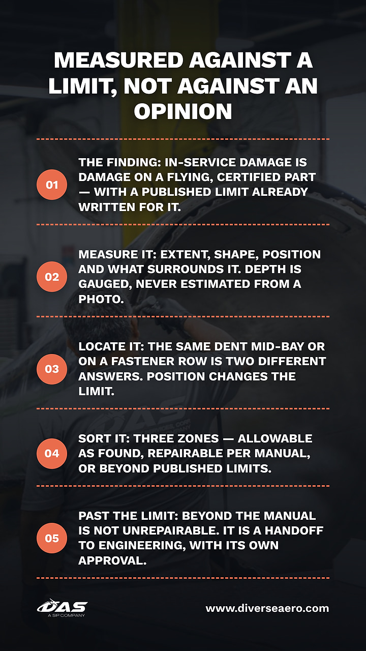
The same dent gives two different answers depending on where it sits, and this is the single most common source of surprise for an operator reading a disposition.
Structure is not uniformly loaded. Skin in the middle of a bay carries a share of the load and is backed up by everything around it. Skin over a splice, at a stringer run-out, near a cutout or on a highly loaded joint carries a concentrated share and has fewer neighbors to redistribute it. A limit that is generous mid-bay tightens sharply as the damage approaches those features — and the manual expresses that as a distance, not as a judgment call.
The same logic governs how size is read in regulation. Under US rules, the repair of damaged areas in stressed covering exceeding six inches in any direction is classed as an airframe major repair, alongside repairs to spars, stringers, ribs and other primary members. Size and position together decide not only the repair, but what the repair is called on paper — and with it, how the repair gets approved and documented.
Measuring what you can see is the start, not the answer.Impact on a composite panel can leave a barely visible surface mark over internal delamination or crushed core. Impact on a metallic skin can leave asmooth dent with cracking initiating under a fastener head. Corrosion measured at the surface says nothing about how far it has spread under the coating.
That is why the disposition follows a mapping step, not aglance. Establishing the real boundary of the damage is what makes thecomparison against a limit meaningful in the first place — and it is covered indetail in our guide to structural inspectionmethods(https://www.diverseaero.com/post/aircraft-structural-inspection-methods).
This is the most expensive misreading in the discipline, and it happens weekly.
When damage falls outside what the structural repair manual covers, the manual has stopped answering. That is all it means. The manual is a set of pre-substantiated repairs, not an inventory of everything the structure can survive. Damage outside it moves to engineering, where a repair can be designed and substantiated for that specific part, that specific damage and that specific aircraft — and approved through a recognized route.
Read as a verdict, that finding turns into a replacement order and a lead time nobody in the conversation controls. Read correctly, itis a handoff: from a published scheme to an engineered one, with its own approval and its own record. What it changes is the documentation and the timeline, not whether the part has a future.
· Measured length, width and depth, with the instrument noted, not estimated from photographs
· Photographs with a scale reference, including an oblique shot that shows the dent profile
· Position on the part and distance to the nearest fastener row, splice or stiffener
· Whether buckling, cracking or corrosion is present around the damage
· Any previous repair in the same area, with its record
· The applicable manual reference and revision you are working to
Everything after that is a comparison: measured condition against published limit, and then the route that follows from which side of the limit it lands on.
Have a finding youneed dispositioned? Send us the damage report and we will tell you which zone it falls into.